Review Contents
01 Geometric Associativity Across Disciplinary Boundaries
In traditional machine engineering workflows, moving a part model from the conceptual design stage to simulation and CNC machining involves exporting neutral exchange files such as STEP or IGES. Every neutral translation breaks the continuous parent-child history tree, separating geometric faces from their associated load constraints, boundary meshes, and machining toolpaths. When engineering changes occur during physical validation, structural engineers must rebuild simulation meshes from scratch while manufacturing teams manually reprogram tool vectors.
Integrated CAD/CAM/CAE platforms eliminate these file transfer gaps by running numerical solvers and manufacturing strategies directly against the underlying mathematical B-Rep definition. Any change applied to a wall thickness, hole diameter, or fillet radius updates throughout the entire computational model. The downstream finite element meshes flex according to the revised solid boundary, while the toolpath generator recalculates pocketing clearances without human intervention.
Seamless Pipeline Insight
Direct geometric associativity preserves topology IDs throughout parametric updates. This eliminates boundary condition displacement errors during finite element remeshing, safeguarding critical contact definitions across multi-body linkages.
02 Stress State Validation and Adaptive Toolpath Regeneration
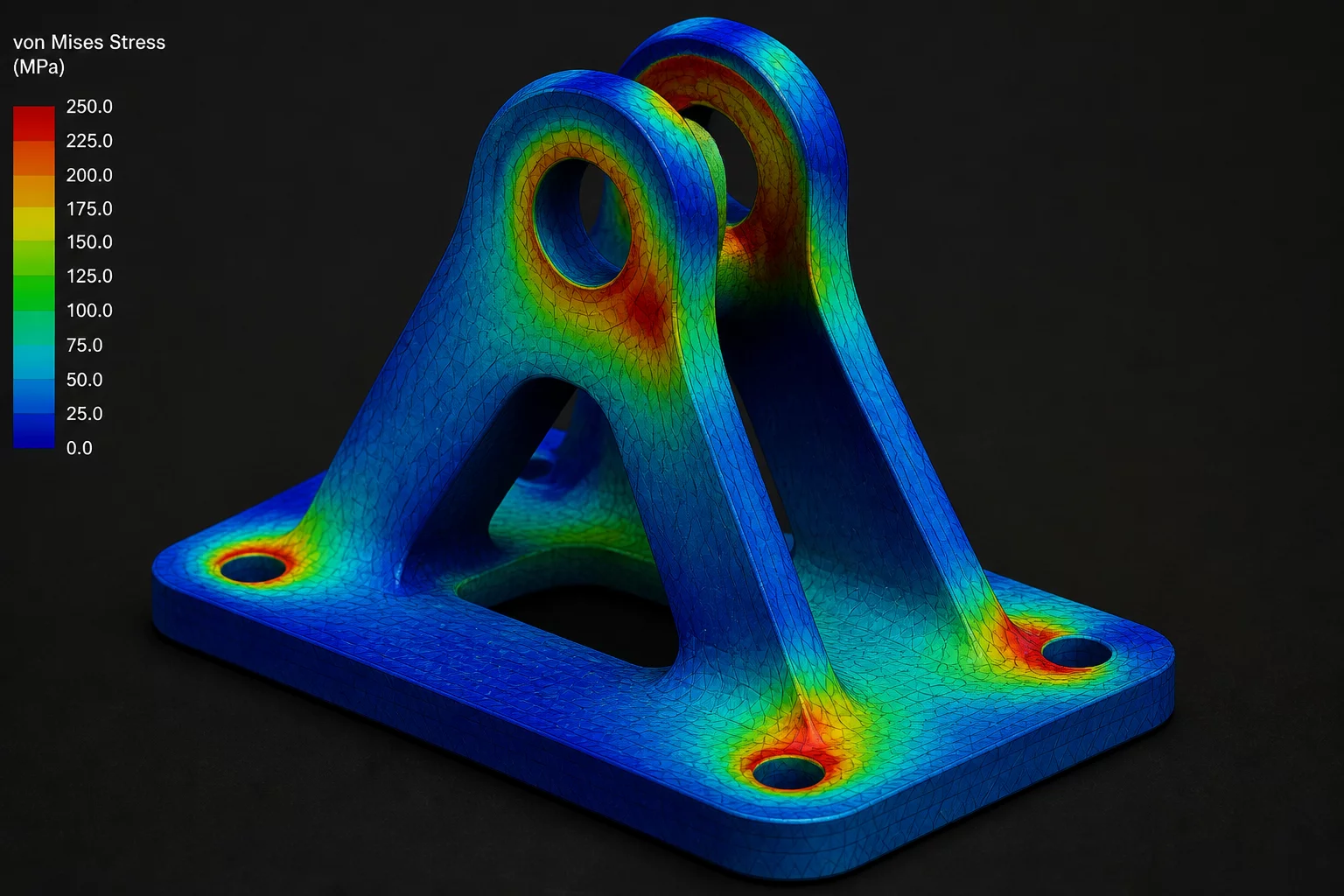
During our benchmark review of a heavy industrial actuator assembly, structural loading analyses identified excessive shear concentration in a mounting bracket lug. Adjusting the lug fillet radius from 3.5 mm to 6.0 mm resolved the peak von Mises stress instantly within the CAE workspace. In a disconnected pipeline, such an alteration would demand re-exporting the geometry, re-applying boundary fixtures, and restructuring the CNC roughing and finishing paths.
- Persistent Mesh Seed Points: Local refinement zones and curvature-based mesh densities remained tethered to the altered fillets without manual node rearrangement.
- Adaptive 5-Axis Clearing: The integrated CAM engine identified the expanded radius and updated the ball-nose cutter engagement angle automatically to prevent tool shank collisions.
- Real-Time Interference Auditing: Dynamic clearance checks flagged an adjacent fastener head proximity issue before the design passed to prototype machining.
Because the stress concentration data and manufacturing path strategies reside inside the shared database, iteration cycles shrunk from several days to under twenty minutes. This immediate feedback loop ensures mechanical reliability without disrupting downstream shop floor schedules.
03 Practical Change Control Protocols for Multi-Physics Assemblies
Tight software integration increases design velocity, but it also raises the risk of accidental downstream modifications if change governance is weak. When a CAD technician shifts a mounting datum to satisfy clearance constraints, that change immediately impacts both the stiffness calculations and the fixture holding setups. Engineering teams require structured change notification protocols to verify ripple effects before releasing updated models to production.
High-performing engineering groups enforce state branch branching and milestone freezes inside their CAD/CAM/CAE databases. Geometric revisions remain in an isolated sandbox until FEA safety factors and CAM cycle times receive multi-departmental approval. Once approved, the master model merges downstream changes reliably across all documentation, toolpaths, and quality inspection programs.
06 Technical Comments & Review
Peer review observations and engineering methodology inquiries.
No comments yet. This could be your first comment.
Leave a Comment
Join the discussion with other CAD specialists and design engineers.