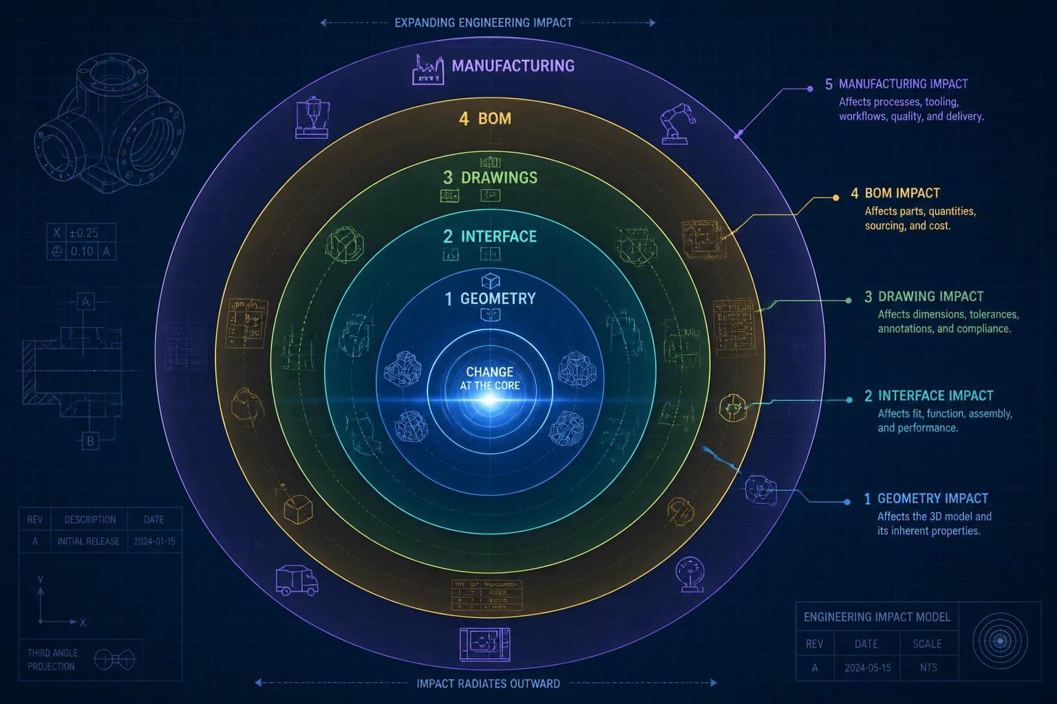
Investigation Structure
01 Origin of the Shift: The Fastener Clearance Dilemma
In high-load mechanical housings, minor adjustments often seem harmless during initial sketch revisions. In this documented industrial case, a design engineer enlarged a locating through-hole from 8.5 mm to 10.5 mm to accommodate an M10 high-tensile shoulder bolt instead of the previously planned M8 socket head screw. The alteration took less than ten seconds inside the Part Studio sketch editor.
While the local clearance issue was solved immediately, the structural bracket retained historical sketch relationships referencing external datum planes. When the feature rebuilt, the outward expansion of the hole boundary reduced the remaining ligament wall thickness below the mandatory 3.2 mm safety threshold, initiating an unmonitored stress concentration zone under dynamic cyclic load tests.
Critical Engineering Insight
Never treat a bore diameter modification as an isolated scalar variable. Changing hole geometry directly alters edge margins, countersink clearances, fastener torque limits, and the spatial keep-out zones required for assembly socket heads.
02 The Parametric Avalanche Across Downstream Trees
Because modern enterprise assemblies rely on parent-child reference geometry, the 2 mm diameter expansion cascaded through three primary layers of downstream dependencies:
- Mating Flange Alignment: The clearance bore in the receiving cast-iron plate had to expand proportionally, which broke the concentric fastener mate constraints in the top-level assembly.
- CAM Toolpath & Tooling Invalidation: The CNC drill cycle designated for the 8.5 mm carbide bit was rendered obsolete, requiring a re-post of the G-code and reassignment of the custom spot-facing tool.
- Automated Bill of Materials (BOM) Mutation: Standard hardware item codes flipped from ISO 4762 M8x35 to ISO 4762 M10x40, triggering procurement discrepancies with suppliers holding pre-allocated batch orders.
Furthermore, the secondary GD&T feature control frames on three production drafting sheets lost their datum target alignments. Without real-time change tracking, these broken annotations remained silent until first-article inspection on the shop floor.
03 Lessons in Engineering Change Order (ECO) Containment
To prevent silent dimensional drift, engineering teams must establish strict boundary verification protocols. Automated version diffing and topological dependency mapping allow designers to visualize every downstream model, drawing, and fixture impacted before committing changes to the main production branch.
By treating every single dimensional modification as a multi-disciplinary event—affecting stress analysts, CAM programmers, and purchasing managers—organizations can eliminate costly rework cycles and prevent prototype scrapping before metal is cut.
Elena Marchetti
Lead ArchitectThis article hits right at the core of why isolated sketch edits without top-down skeleton control are hazardous. We experienced an identical situation with an indexing pin bore last quarter.