Table of Contents
01 The Bottleneck of Manual Aerodynamic Profiling
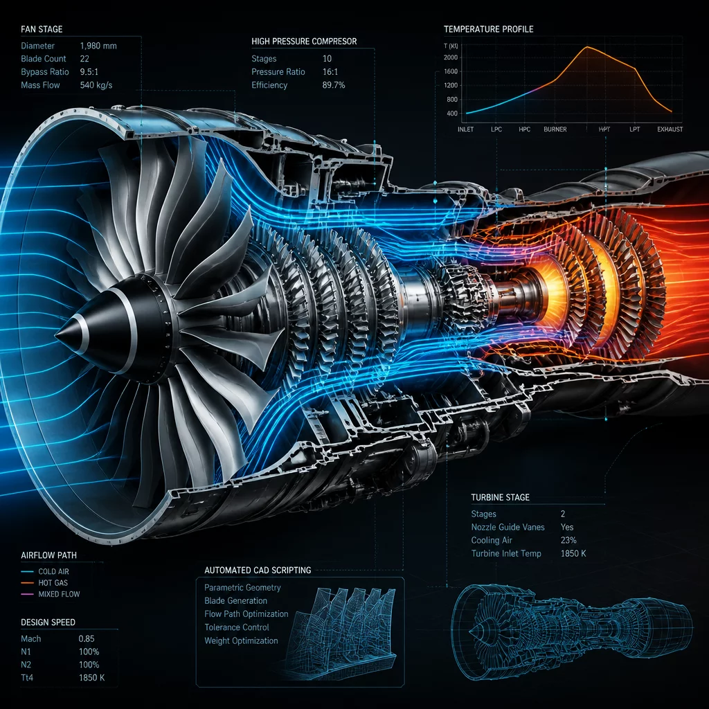
Gas turbine design begins at the gas path: the annular duct where thermodynamic expansion drives multi-stage compressor and turbine wheels. In conventional workflows, propulsion engineers export aerodynamic meridional point clouds from 1D mean-line codes, manually importing curve coordinates into 3D CAD platforms to loft blading surfaces. This repetitive hand-off introduces geometric translation errors, consumes weeks per design iteration, and slows responsive aerodynamic optimization.
When thermodynamic cycle calculations demand a minor alteration in mass flow rate or stage pressure ratio, manual CAD updates require complete rebuilds across dozens of stator vanes, rotor blades, casing shrouds, and internal cooling bleed ports. A single late-stage modification frequently breaks geometric dependencies, desynchronizing structural finite element analysis and computational fluid dynamics (CFD) grids.
Key Engineering Takeaway
Automated flow path generation binds mean-line thermodynamic boundary equations directly to parametric surface lofts, eliminating manual point-cloud re-lofting and ensuring complete associativity across multi-stage assemblies.
02 Algorithmic Scripting and Flow Path Parametrization
Modern turbomachinery teams implement programmatic scripting routines to govern meridional gas path geometry automatically. By exposing CAD feature parameters to custom Python and computational design scripts, hub and shroud contours update dynamically in response to thermodynamic pressure and temperature gradients:
- Meridional Duct Lofting: Non-uniform rational B-splines (NURBS) define casing contours with continuous curvature (G2/G3 continuity), preventing boundary-layer separation induced by facet discontinuities.
- Automated Stagger and Camber Distribution: Parametric chord lines, leading edge radii, and trailing edge wedge angles adjust along spanwise stations through programmatic spline transformation matrices.
- Variable Fillet and Tip Clearance Rules: Scripted blend routines compute thermal expansion-compensated clearances at blade tips and root fillets according to centrifugal load distributions.
The resulting model maintains a live parametric link back to the thermodynamic cycle database. As aerodynamicists adjust stage reaction values, downstream rotor discs, cooling cavity volumes, and seal tooth clearances recalculate without geometry rebuild failures.
03 Downstream Mesh Integration & Manufacturing Verification
High-fidelity turbomachinery development demands robust downstream interoperability. Automated flow path geometry exports directly into structured CFD meshing suites without requiring manual surface healing, topological stitching, or non-manifold edge suppression. Standardized surface tagging flags suction sides, pressure surfaces, periodic boundaries, and inlet-outlet interfaces automatically upon generation.
For manufacturing hand-off, programmatic coordinate extraction compiles 5-axis CNC milling toolpaths and additive manufacturing support envelopes directly from the validated CAD master model. Real-world validation runs demonstrate that automated gas path scripting cuts total cycle lead times by over 70%, liberating propulsion engineers to evaluate hundreds of aerodynamic design variants in the time previously spent rebuilding a single turbine stage.
Elena Marchetti
Lead ArchitectThe precision engineering workflows and procedural parametric layouts exceeded all preliminary metrics. We integrated the structural model directly into our analysis pipeline with zero geometric conversion losses.